|
Projects
|
|
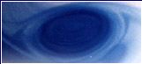
| Figure
1. We are looking from above at an upstream region
and a channel. These are held in a larger two-meter diameter
cylindrical catch basin on a rotating turntable. The very
flat channel bottom was produced using plate glass, painted
black, carefully leveled and elevated about 20 cm above
the bottom. Water lying under the atmosphere was used
for this experiment. Depth of the water over the channel
was deep enough (two cm, say) so that the Rossby Radius
of the water layer was less than the width of the channel.
Sides were attached to the flat bottom. The marks on the
channel wall (to the right of the direction of flow, which
is at the bottom of this view) are cm marks. The channel
was connected to a deeper upstream region on the left
with a bottom sloping up to the channel. Water was pumped
into the upstream region until it filled the basin and
spilled out through the channel. The source is located
near the bottom left of this photograph. Instead of the
water flowing directly up the sloping bottom to the channel,
it flows to the other upstream wall at the top left of
this photograph and then moves along that wall to the
channel. Once it arrives at the flat region the water
veers to the right-hand wall of the channel (looking downstream).
The result is that there is a region of almost zero flow
in the upstream region that lies between the upstream
current and the current in the channel. This region corresponds
to upstream gyres predicted theoretically. |
|
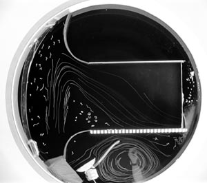
| Figure
2. We are looking from the side of a cylindrical
tank filled with kerosene in the bottom and a water-alcohol
mixture at the top. An upstream region is separated from
downstream by a vertical wall with a channel. Bottom fluid
is pumped into the bottom of the upstream basin and it
returns through the channel. In this view, the returning
flow is coming toward us. This illustrates three features
of such flows: 1. Upstream circulation, as shown by the
circular front. 2. Tilt of the interface in the passage.
3. Turbulence in the downstream basin. |
|
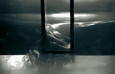
| Figure
3. This shows a side view of a current of blue
dense water in clear rotating ambient water. The current
emerges from the passage, flows down the slope, bends
to its right as it flows because of rotation and develops
roll waves. |
|
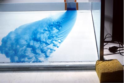
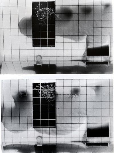
| Figure
4. This is a top view of a rotating current of
dyed dense water in clear ambient water over a sloping
bottom. The shallow end is at the top of the picture,
and the source of the current was located at the top right.
The current breaks up into eddies. These consist of a
lens of dense water lying on the sloping bottom. The lenses
drift toward the left in this picture, and they have cyclonic
circulation in the clear water overhead. This circulation
is visible as time-exposure streaks from surface pellets
as the lens drifts over the black bottom. The bottom picture
is some tens of seconds after the top. |
Laboratory studies relevant to overflow
dynamics
J.A. Whitehead
Saddle points between neighboring deep ocean basins are the
sites of unidirectional flow from one basin to the next, depending
on the source of bottom water. We show four laboratory studies
that have been designed to illuminate dynamics of such flows
in the ocean. As expected, processes due to effects of rotation
are found when Rossby radius is less than a typical lateral
length-scale.
|
|